


Decommissioned SuperMUC
SuperMUC Petascale System
SuperMUC is the name of the high-end supercomputer at the Leibniz-Rechenzentrum (Leibniz Supercomputing Centre) in Garching near Munich (the MUC suffix is borrowed from the Munich airport code). With more than 241,000 cores and a combined peak performance of the two installation phases of more than 6.8 Petaflop/s (=1015 Floating Point Operations per second), it is one of the fastest supercomputers in the world.
System purpose and target users
SuperMUC strengthened the position of Germany's Gauss Centre for Supercomputing in Europe by delivering outstanding compute power and integrating it into the European High Performance Computing ecosystem. With the operation of SuperMUC, LRZ, acted as a European Centre for Supercomputing and was a Tier-0 centre for PRACE, the Partnership for Advanced Computing in Europe. SuperMUC was available to all European researchers to expand the frontiers of science and engineering.
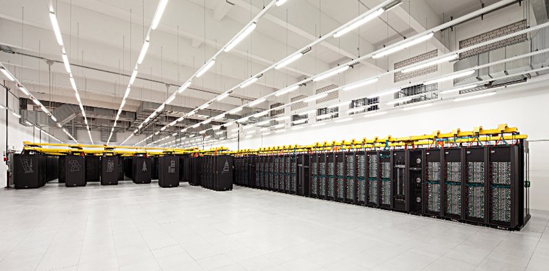
Figure: SuperMUC Phase 1 and Phase 2 in the computer room.
System Configuration Details
LRZ's target for the architecture was a combination of a large number of thin and medium sized compute nodes with 32 GByte (Phase 1) and 64 GByte (Phase 2) of memory, respectively, and a smaller number of fat compute nodes with 256 GByte memory. The network interconnect between the nodes allowed excellent scaling of parallel applications up to the level of more than 10,000 tasks.
SuperMUC Phase 1 consisted of 18 Thin Node Islands based on Intel Sandy Bridge-EP processor technology, 6 Thin Node Islands based on Intel Haswell-EP processor technology and one Fat Node Island based on Intel Westmere-EX processor technology. Each Island contained more than 8,192 cores. All compute nodes within an individual Island were connected via a fully non-blocking Infiniband network (Phase 1: FDR10 for the Thin nodes of Phase 1, FDR14 for the Haswell nodes of Phase 2 and QDR for the Fat Nodes). Above the Island level, the pruned interconnect enabled a bi-directional bi-section bandwidth ratio of 4:1 (intra-Island / inter-Island). In addition, SuperMIC, a cluster of 32 Intel Ivy Bridge-EP nodes each having two Intel Xeon Phi accelerator cards was installed, which was also part of the SuperMUC system.
Technical data
| Installation Phase | Phase 1 (decomissioned end of 2018) | Phase 2 (decomissioned end of 2019) | ||
|---|---|---|---|---|
| Installation Date | 2011 | 2012 | 2013 | 2015 |
Islandtype | Fat Nodes | Thin Nodes | Many Cores Nodes | Haswell Nodes |
| System | BladeCenter HX5 | IBM System x iDataPlex dx360M4 | IBM System x iDataPlex dx360M4 | Lenovo NeXtScale nx360M5 WCT |
| Processor Type | Westmere-EX Xeon E7-4870 10C | Sandy Bridge-EP Xeon E5-2680 8C | Ivy-Bridge and Xeon Phi 5110P | Haswell Xeon Processor E5-2697 v3 |
| Nominal Frequency [GHz] | 2.4 | 2.7 | 1.05 | 2.62 |
| Performance per core | 4 DP Flops/cycle = 9.6 DP GFlop/s 2-wide SSE2 add + 2-wide SSE2 mult | 8 DP Flops/cycle = 21.6 DP GFlops/s 4-wide AVX add + 4-wide AVX mult | 16 DP Flops/cycle = | 16 DP Flops/cycle = |
| Total Number of nodes | 205 | 9216 | 32 | 3072 |
| Total Number of cores | 8,200 | 147,456 | 3,840 (Phi) | 86,016 |
| Total Peak Performance [PFlop/s] | 0.078 | 3.2 | 0.064 (Phi) | 3.58 |
| Total Linpack Performance [PFlop/s] | 0.065 | 2.897 | n.a. | 2.814 |
| Total size of memory [TByte] | 52 | 288 | 2.56 | 194 |
| Total Number of Islands | 1 | 18 | 1 | 6 |
| Typical Power Consumption [MW] | < 2.3 | ~1.1 | ||
| Components | ||||
| Nodes per Island | 205 | 512 | 32 | 512 |
| Processors per Node | 4 | 2 | 2 (IvyB) 2.6 GHz + 2 Phi 5110P | 2 |
| Cores per Processor | 10 | 8 | 8 (IvyB) + 60 (Phi) | 14 |
| Cores per Node | 40 | 16 | 16 (host) + 120 (Phi) | 28 |
| Logical CPUs per Node (Hyperthreading) | 80 | 32 | 32 (host) + 480 (Phi) | 56 |
| Memory and Caches | ||||
| Memory per Core [GByte] (typically available for applications) | 6.4 (~6.0) | 2 (~1.5) | 4 (host) + 2 x 0.13 (Phi) | 2.3 (2.1) |
| Size of shared Memory per node [GByte] | 256 | 32 | 64 (host) + 2 x 8 (Phi) | 64 |
| Bandwidth to Memory per node [Gbyte/s] | 136.4 | 102.4 | Phi: 384 | 137 |
| Level 3 Cache Size (shared) [Mbyte] | 4x30 | 2x20 | 4x18 | |
| Level 2 Cache Size per core [kByte] | 256 | 256 | Phi: 512 | 256 |
| Level 1 Cache Size [kByte] | 32 | 32 | 32 | 32 |
| Latency Access Memory [cycles] / Bandwidth per core [GB/s] | ~160 /8.8 | ~200 / 6.7 | ||
| Level 3 Latency [cycles] /BW per Core [GB/s] | ~ 30 / 31 | 36 / 39 | ||
Level 2 Latency [cycles]1 /BW per Core [GB/s] | 12 / 42 | 12 / 92 | ||
Level 1 Latency [cycles]1 /BW per Core [GB/s] | 4 | 4 /130 | 4 / 343 | |
| Interconnect | ||||
| Technology | Infiniband QDR | Infiniband FDR10 | Infiniband FDR10 | Infiniband FDR14 |
| Intra-Island Topology | non-blocking Tree | non-blocking Tree | ||
| Inter-Island Topology | Pruned Tree 4:1 | n.a. | Pruned Tree 4:1 | |
| Bisection bandwidth of Interconnect [TByte/s] | 12.5 | 5.1 | ||
| Servers | ||||
| Login Servers for users | 2 | 7 | 1 | 5 |
| Storage | ||||
| Size of parallel storage (SCRATCH/WORK) [Pbyte] | 15 | |||
| Size of NAS storage (HOME) [PByte] | 3.5 (+ 3.5 for replication) | |||
| Aggregated bandwidth to/from parallel storage [GByte/s] | 250 | |||
| Aggregated bandwidth to/from NAS storage [GByte/s] | 12 | |||
| Capacity of Archive and Backup Storage [PByte] | > 30 | |||
| System Software | ||||
| Operating System | Suse Linux Enterprise Server (SLES) | |||
| Batchsystem | IBM Loadleveler | |||
| Parallel Filesystem for SCRATCH and WORK | IBM GPFS | |||
| File System for HOME | NetApp NAS | |||
| Archive and Backup Software | IBM TSM | |||
| System Management | xCat from IBM | |||
| Monitoring | Icinga, Splunk | |||
1:Latency is much longer, if data are also in L1 or L2 of other core.
2: With each new processor line, Intel introduces new architecture optimizations.
The design of the “Haswell” architecture acknowledges that highly-parallel/vectorized applications place the highest load on the processor cores (requiring more power and thus generating more heat). While a CPU core is executing intensive vector tasks (AVX instructions), the clock speed may be reduced to keep the processor within its power limits (TDP). In effect, this may result in the processor running at a lower frequency than the “base” clock speed advertised for each model. For that reason, each “Haswell” processor model is assigned two “base” frequencies:
- AVX mode: due to the higher power requirements of AVX instructions, clock speeds may be somewhat lower while executing AVX instructions
- Non-AVX mode: while not executing AVX instructions, the processor will operate at what would traditionally be considered the “stock” frequency
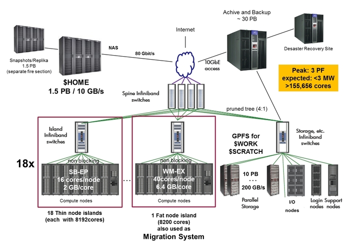
Figure: Schematic view of SuperMUC Phase1
SuperMUC Phase1 and Phase2 were only loosely coupled through the GPFS and NAS File systems, used by both Phase 1 and Phase 2. It was not possible to run one single job across Phase1 and Phase2. The scheduling and job classes of Phase1 and Phase2 were different. However, Phase1 and Phase2 shared the same programming environment.
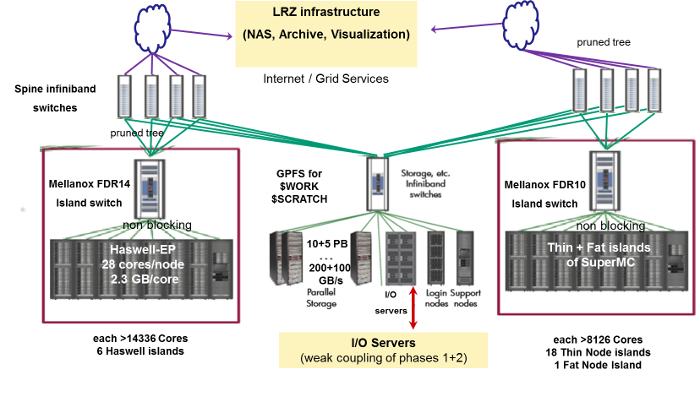
Figure: Schematic view of SuperMUC Phase1 + Phase2.
Energy Efficiency by Warm Water cooling
SuperMUC used a new, revolutionary form of warm water cooling developed by IBM. Active components like processors and memory were directly cooled with water that could have an inlet temperature of up to 40 degrees Celsius. This "High Temperature Liquid Cooling" together with very innovative system software cut the energy consumption of the system up to 40%. In addition, LRZ buildings were heated re-using this energy.
Why "warm" water cooling?
Typically water used in data centers has an inlet temperature of approx 16 degrees Celsius and, after leaving the system, an outlet temperature of approx. 20 degrees Celsius. To make water with 16 degrees Celsius requires complex and energy-hungry cooling equipment. At the same time there is hardly any use for the warmed-up water as it is too cold to be uses in any technical processes.
SuperMUC allowed an increased inlet temperature. It was easily possible to provide water having up to 40 degrees Celsius using simple "free-cooling" equipment as outside temperatures in Germany hardly ever exceed 35 degrees Celsius. At the same time the outlet water could be made quite hot (up to 70 degrees Celsius) and re-used in other technical processes - for example to heat buildings or in other technical processes.
By reducing the number of cooling components and using free cooling LRZ was able to save several millions of Euros in cooling costs over the 5-year lifetime of the system.
Storage Systems
SuperMUC had a powerful I/O-Subsystem which helped to process large amounts of data generated by simulations.
Home file systems
Permanent storage for data and programs was provided by a 16-node NAS cluster from NetApp. This primary cluster had a capacity of 3.5 Petabytes and demonstrated an aggregated throughput of more than 12 GB/s using NFSv3. Netapp's Ontap 8 "Cluster-mode" provided a single namespace for several hundred project volumes on the system. Users could access multiple snapshots of data in their home directories.
Data was regularly replicated to a separate 4-node Netapp cluster with another 3.5 PB of storage for recovery purposes. Replication used Snapmirror-technology and ran with up to 2 GB/s in this setup.
Storage hardware consisted of >3,400 SATA-Disks with 2 TB each, protected by double-parity RAID and integrated checksums.
Work and Scratch areas
For high-performance I/O, IBM's General Parallel File System (GPFS) with 12 PB of capacity and an aggregated throughput of 250 GB/s was available.